Wednesday, 18 February 2015

TABLE OF CONTENTS


 I. PLC BASICS.

 1. An Overall Look at Programmable Logic Controllers.

 2. The PLC: A Look Inside.
 3. General PLC Programming Procedures.
 4. Devices to Which PLC Input and Output Modules Are Connected.
 6. Relation of Digital Gate Logic to Contact/Coil Logic.
 7. Creating Ladder Diagrams from Process Control Descriptions.
 9. PLC Timer Functions.
10. PLC Counter Functions.

II. BASIC PLC PROGRAMMING.

  Programming On-Off Inputs to Produce On-Off Outputs.

III. BASIC PLC FUNCTIONS.

  Register Basics.

AN OVER ALL LOOK AR PLC

How PLCs Work

A programmable logic controller is a specialized computer used to control machines and processes.  It therefore shares common terms with typical PCs like central processing unit, memory, software and communications.  Unlike a personal computer though the PLC is designed to survive in a rugged industrial atmosphere and to be very flexible in how it interfaces with inputs and outputs to the real world.
The components that make a PLC work can be divided into three core areas.
  • The power supply and rack
  • The central processing unit (CPU)
  • The input/output (I/O) section
PLCs come in many shapes and sizes.  They can be so small as to fit in your shirt pocket while more involved controls systems require large PLC racks.  Smaller PLCs (a.k.a. “bricks”) are typically designed with fixed I/O points.  For our consideration, we’ll look at the more modular rack based systems.  It’s called “modular” because the rack can accept many different types of I/O modules that simply slide into the rack and plug in.

 PLC angled with doors closed and text

The Power Supply and Rack

So let’s start off by removing all our modules which leaves us with a naked PLC with only the power supply and the rack
 PLC empty rack with text

The rack is the component that holds everything together.  Depending on the needs of the control system it can be ordered in different sizes to hold more modules.  Like a human spine the rack has a backplane at the rear which allows the cards to communicate with the CPU.  The power supply plugs into the rack as well and supplies a regulated DC power to other modules that plug into the rack.  The most popular power supplies work with 120 VAC or 24 VDC sources.


SLC500 CPU components


Since a PLC is a dedicated controller it will only process this one program over and over again.  One cycle through the program is called a scan time and involves reading the inputs from the other modules, executing the logic based on these inputs and then updated the outputs accordingly.  The scan time happens very quickly (in the range of 1/1000th of a second).  The memory in the CPU stores the program while also holding the status of the I/O and providing a means to store values.


CPU operating cycle


I/O System


The I/O system provides the physical connection between the equipment and the PLC.  Opening the doors on an I/O card reveals a terminal strip where the devices connect.


PLC face with doors open


There are many different kinds of I/O cards which serve to condition the type of input or output so the CPU can use it for it’s logic.  It's simply a matter of determining what inputs and outputs are needed, filling the rack with the appropriate cards and then addressing them correctly in the CPUs program.
 PLC inserting card

Inputs

Input devices can consist of digital or analog devices.  A digital input card handles discrete devices which give a signal that is either on or off such as a pushbutton, limit switch, sensors or selector switches.  An analog input card converts a voltage or current (e.g. a signal that can be anywhere from 0 to 20mA) into a digitally equivalent number that can be understood by the CPU.  Examples of analog devices are pressure transducers, flow meters and thermocouples for temperature readings.

Outputs

Output devices can also consist of digital or analog types.  A digital output card either turns a device on or off such as lights, LEDs, small motors, and relays.  An analog output card will convert a digital number sent by the CPU to it’s real world voltage or current.  Typical outputs signals can range from 0-10 VDC or 4-20mA and are used to drive mass flow controllers, pressure regulators and position controls


Programming a PLC

In these modern times a PC with specially dedicated software from the PLC manufacturer is used to program a PLC.  The most widely used form of programming is called ladder logic.  Ladder logic uses symbols, instead of words, to emulate the real world relay logic control, which is a relic from the PLC's history.  These symbols are interconnected by lines to indicate the flow of current through relay like contacts and coils.  Over the years the number of symbols has increased to provide a high level of functionality. 
The completed program looks like a ladder but in actuality it represents an electrical circuit.  The left and right rails indicate the positive and ground of a power supply.  The rungs represent the wiring between the different components which in the case of a PLC are all in the virtual world of the CPU.  So if you can understand how basic electrical circuits work then you can understand ladder logic.
In this simplest of examples a digital input (like a button connected to the first position on the card) when it is pressed turns on an output which energizes an indicator light.


Simple ladder logic example


The completed program is downloaded from the PC to the PLC using a special cable that’s connected to the front of the CPU.  The CPU is then put into run mode so that it can start scanning the logic and controlling the outputs.


THE PLC: "A LOOK INSIDE"


PLCs allow the automation of electromechanical processes such as those used to control machinery on factory assembly lines, amusement rides, or centrifuges for separating nuclear material. Exploiting four zero-day flaws,Stuxnet functions by targeting machines using the Microsoft Windows operating system and networks, then seeking out Siemens Step7 software. Stuxnet reportedly compromised Iranian PLCs, collecting information on industrial systems and causing the fast-spinning centrifuges to tear themselves apart.Stuxnet’s design and architecture are not domain-specific and it could be tailored as a platform for attacking modern SCADA and PLC systems (e.g. in the automobile or power plants), the majority of which reside in Europe, Japan and the US.[4]
Stuxnet reportedly ruined almost one-fifth of Iran's nuclear centrifuges.
Stuxnet has three modules: a worm that executes all routines related to the main payload of the attack; a link file that automatically executes the propagated copies of the worm; and a rootkit component responsible for hiding all malicious files and processes, preventing detection of the presence of Stuxnet.
Stuxnet is typically introduced to the target environment via an infected USB flash drive. The virus then propagates across the network, scanning for Siemens Step7 software on computers controlling a PLC. In the absence of both criteria, Stuxnet becomes dormant inside the computer. If both the conditions are fulfilled, Stuxnet introduces the infected rootkit onto the PLC and Step7 software, modifying the codes and giving unexpected commands to the PLC while returning a loop of normal operations system values feedback to the users.
Some more complex PLC’s look a little different, but EVERY PLC will have the following components:
1. A set of electrical connections corresponding to INPUTS. Each connection has a unique INPUT number.
2. A set of electrical connections, corresponding to OUTPUTS. Each connection has a unique OUTPUT number.
3. A Controller, which is a simple form of a computer.

What can a PLC do ?


Execute logic to control equipment based on some conditions which are reported by sensors, or switches. This needs some explanation. Consider that there is some equipment in a factory which needs to be controlled by some actuators. For example, when a part is loaded on a machine, we would like two pneumatic cylinders to extend and hold the part into a fixed position. Then we would like to turn on a motor, which operates a drill to make holes in the part. When the drilling is done, we would like to switch off the drill, and then release the cylinders, to remove the part.

Imagine that when a part is put on the machine table, a photo-sensor is activated, giving us an indication that the operation sequence described above must begin.
Then we can use a PLC to operate all this machinery.

First, the photosensor gives the signal of part arrival: it is therefore an input to our logic, indicating that operations must begin. Such sensors are usually connected to the INPUT connections on the PLC (since these sensors are external to the PLC, they are also called EXTERNAL INPUTS).

The logical sequence of operations: Turn Cylinder 1 ON -> Turn Cylinder 2 ON -> Turn Drill Motor ON -> Wait (delay) till Drilling is done -> Turn Drill Motor OFF -> Turn Cylinder 2 OFF -> Turn Cylinder 1 OFF must now be executed. All this is information is very systematic, and therefore we can program it into a computer to perform the operation. This information is then EXECUTED (just like a computer RUNNING a PROGRAM) by the computer inside the PLC. This computer is called a CONTROLLER (since it controls the logic).
Thus, when the EXTERNAL INPUT connected to the Photo Sensor is turned ON, the PLC controller senses that actions must begin, and it first turns a SPECIFIED OUTPUT terminal (for example, Output 1), ON. This means that at the electrical connection corresponding to Output 1, the voltage level, which was 0volts before, is now turned HIGH (example, 24 Volts). Of course, we had connected this Output 1 connection with a wire to a solenoid valve controlling the Cylinder 1. Thus Cylinder 1 will now turn ON.
Again, since the terminal Output 1 is connected to a device (in this case, a solenoid) outside the PLC, we call it an EXTERNAL OUTPUT terminal.
Similarly, we had connected (external) Output 2 to a solenoid controlling Cylinder 2. And Output 3 to the motor driving the Drilling Machine. Thus, CONTROLLER, in sequence specified by the LOGIC PROGRAMMED by you, controls the External Outputs to go ON and OFF. And accordingly, the different actuators connected to the External Outputs are turned ON and OFF.

Can the PLC control many different actuators ? Yes ! It can control as many actuators as it has External Output terminals.

What kind of logical sequences of operations (including repeating actions, or loops) can the PLC control ? Many, and we will now learn these.

Example 1:


Let’s start with the simplest example. In our factory is a robot, which picks up heavy metal parts from one place, and puts them in another place. When the robot is working, it is not safe for humans to go near it, since there could be an accident. Therefore, to warn the human operator that they are too close to the operating robot, we need to install a warning light.

On the floor close to the Robot’s operational area, we put a pressure sensitive mat. This mat has a pressure sensor, so when the load on top of it is increased (for example, when a human steps on the mat) then the pressure switch is activated and turns ON.

THE LOGIC:

When Pressure_Switch is ON, turn the Warning_Light ON.

(of course, when the pressure switch turns off again, that is, when the human goes away from the robot, the warning light must also go off.)


STEP 1:

We write this logic into a PROGRAM (since the computer can only understand programs!).

STEP 2:

We load this program into the PLC.

STEP 3:

We connect the sensor output (in this case, the Output of the Pressure sensitive switch) to the External Input terminal. Of course, we have more than one External Input terminals. Which one do we connect ? The one we specified in our program !

STEP 4:

We connect the PLC External Output Terminal (specified by our program) to the Warning Light.

STEP 5:

Now, we EXECUTE the logic program on the PLC.

GENERAL PLC PROGRAMMING PROCEDURES


Ladder logic is the main programming method used for PLCs. As mentioned before, ladder logic has been developed to mimic relay logic. The decision to use the relay logic diagrams was a strategic one. By selecting ladder logic as the main programming method, the amount of retraining needed for engineers and tradespeople was greatly reduced.
Modern control systems still include relays, but these are rarely used for logic. A relay is a simple device that uses a magnetic field to control a switch, as pictured in See Simple Relay Layouts and Schematics. When a voltage is applied to the input coil, the resulting current creates a magnetic field. The magnetic field pulls a metal switch (or reed) towards it and the contacts touch, closing the switch. The contact that closes when the coil is energized is called normally open. The normally closed contacts touch when the input coil is not energized. Relays are normally drawn in schematic form using a circle to represent the input coil. The output contacts are shown with two parallel lines. Normally open contacts are shown as two lines, and will be open (non-conducting) when the input is not energized. Normally closed contacts are shown with two lines with a diagonal line through them. When the input coil is not energized the normally closed contacts will be closed (conducting).
Plc intro-3.svg Plc intro-2.svg  

Relays are used to let one power source close a switch for another (often high current) power source, while keeping them isolated. An example of a relay in a simple control application is shown in See A Simple Relay Controller. In this system the first relay on the left is used as normally closed, and will allow current to flow until a voltage is applied to the input A. The second relay is normally open and will not allow current to flow until a voltage is applied to the input B. If current is flowing through the first two relays then current will flow through the coil in the third relay, and close the switch for output C. This circuit would normally be drawn in the ladder logic form. This can be read logically as C will be on if A is off and B is on.he first PLCs were programmed with a technique that was based on relay logic wiring schematics. This eliminated the need to teach the electricians, technicians and engineers how to program a computer - but, this method has stuck and it is the most common technique for 
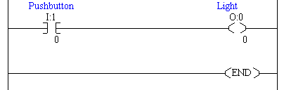
programming PLCs today. An example of ladder logic can be seen in See A Simple Ladder Logic Diagram. To interpret this diagram imagine that the power is on the vertical line on the left hand side, we call this the hot rail. On the right hand side is the neutral rail. In the figure there are two rungs, and on each rung there are combinations of inputs (two vertical lines) and outputs (circles). If the inputs are opened or closed in the right combination the power can flow from the hot rail, through the inputs, to power the outputs, and finally to the neutral rail. An input can come from a sensor, switch, or any other type of sensor. An output will be some device outside the PLC that is switched on or off, such as lights or motors. In the top rung the contacts are normally open and normally closed. Which means if input A is on and input B is off, then power will flow through the output and activate it. Any other combination of input values will result in the output X being off.
 Plc intro-6.svg

A Simple Ladder Logic Diagram

The second rung of See A Simple Ladder Logic Diagram is more complex, there are actually multiple combinations of inputs that will result in the output Y turning on. On the left most part of the rung, power could flow through the top if C is off and D is on. Power could also (and simultaneously) flow through the bottom if both E and F are true. This would get power half way across the rung, and then if G or H is true the power will be delivered to output Y. In later chapters we will examine how to interpret and construct these diagrams.
There are other methods for programming PLCs. One of the earliest techniques involved mnemonic instructions. These instructions can be derived directly from the ladder logic diagrams and entered into the PLC through a simple programming terminal. An example of mnemonics is shown in See An Example of a Mnemonic Program and Equivalent Ladder Logic. In this example the instructions are read one line at a time from top to bottom. The first line 00000 has the instruction LDN (input load and not) for input A. This will examine the input to the PLC and if it is off it will remember a 1 (or true), if it is on it will remember a 0 (or false). The next line uses an LD (input load) statement to look at the input. If the input is off it remembers a 0, if the input is on it remembers a 1 (note: this is the reverse of the LD). The AND statement recalls the last two numbers remembered and if the are both true the result is a 1, otherwise the result is a 0. This result now replaces the two numbers that were recalled, and there is only one number remembered. The process is repeated for lines 00003 and 00004, but when these are done there are now three numbers remembered. The oldest number is from the AND, the newer numbers are from the two LD instructions. The AND in line 00005 combines the results from the last LD instructions and now there are two numbers remembered. The OR instruction takes the two numbers now remaining and if either one is a 1 the result is a 1, otherwise the result is a 0. This result replaces the two numbers, and there is now a single number there. The last instruction is the ST (store output) that will look at the last value stored and if it is 1, the output will be turned on, if it is 0 the output will be turned off.Plc intro-7.svg

DEVICE TO WHICHPLCINPUT AND OUTPUT MODULE ARE CONNECTED


Input and Output Module:-

Inputs carry signals from the field (process) to the controller. Various types of inputs  can be  switches, pressure sensors, transmitters etc. The field devices to whom PLC sends the results of logical operations are the output devices. These are the actuators that  adjusts or control the process,  motors, lights, relays, pumps, etc. Many types of inputs and outputs can be connected to a PLC and they can be categorised mainly as analog and digital. Digital inputs and outputs operate on  discrete or binary change  i.e. on/off, open/close. Analog inputs and outputs change continuously with reference to time.

Programming Device:-

The PLC is programmed using a special software using  computer or  hand Held Terminal(HHT) that can load and change the logic inside.

Operation of a PLC system:-

The operation of the PLC is determined by 3 steps. 
     
  1. Reading the field status form input devices
  2. Execution or solving the logic, and
  3. Updating the output devices status.